|
|
Calculation and physics of scattering states |
![]()
|
Techniques for the calculation of electron scattering states to date
are not fast enough in applications to realistic crystal surfaces.
Two new methods are presented which shall allow to reach the
increasing demands on efficiency, flexibility, and accuracy.
As a spin-off, the calculations provide a very convenient
approach to the interpretation of final state effects in photoemission. At the very low energies of ultraviolet photoelectron spectroscopy the detailed structure of the potential is important. The nonspherical shape near the cores, the modulations between the cores, and the specialities in the surface region all have strong influences on the spectra. The adequate procedure is still in question for the calculation of scattering states in such potentials. Besides the traditional tracing of the multi-scattering processes and the matching procedures, recently direct solutions of the Schrödinger equation have been achieved. This can be done already with a fast method if enough memory is available. However, there is more than one way to construct such a method. It can be composed with components chosen at several steps. Several decisions have to be made:
Now, the following combinations have shown to be feasible:
Besides fast computations with realistic potentials the above methods bear additional advantages since they calculate explicitly the wavefunction. This offers a direct approach for an interpretation of the final state wavefunction's influence in photoemission, which is illustrated by two simple examples.
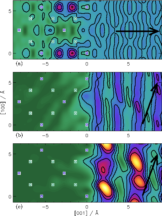
Fig. 1: Contour plots of the Si(001) charge density in the plane of the [100] and [001] directions. The atoms lying in the plane are drawn blue and the projected positions of the remaining atoms are green. The contour levels are the same for all plots. Three different combinations of the emission angle and the final state energy are shown: (a) Efin = 55 eV for normal emission; (b) Efin as before but for a polar angle of 70° and the azimuth in the shown plane; (c) angles as before, but with Efin = 21 eV. The color scale starts at low density with dark green and develops to blue, red, and yellow at high densities. A high quality image is available here.
Fig. 1 shows the charge density of a final state for photoemission.
There is a significant variation of its distribution in the surface region.
It varies with incidence direction and less pronounced also
with energy. This can be directly connected with the escape depth of the
photoelectron or with the surface sensitivity of photoemission:
Electron spectroscopy at inclined angles and at low energies
probes especially the surface properties. This is known and becomes
directly visible here. Additionally, an energy and angle dependent
fine structure is observed which is correlated with the atomic positions.
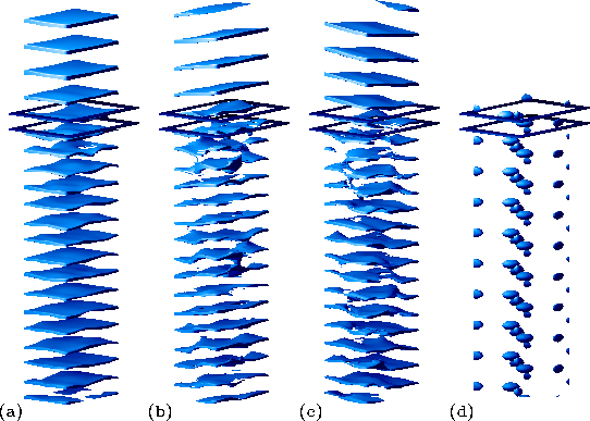 Fig. 2:Perspective view of phase isosurfaces of the GaAs(110) surface. Three different combinations of the emission angle and the final state energy are shown: (a) Efin = 18 eV for normal emission; (b) Efin = 18 eV, polar angle of 17.62°, azimuthal angle of 180°; (c) Efin = 20 eV, polar angle of 17.62°, azimuthal angle of 55° (d) position of the atoms. A unit cell in the surface parallel directions with As atoms at the corners is shown. The surface perpendicular range extends over 3 lattice constants into the vacuum at the top of the images and to 6 lattice constants into the bulk. The additional frames indicate the position of the uppermost two atomic layers.
The change in the phase distribution of the final state is shown in
Fig. 2 by varying the emission direction and excitation energy. The
surfaces of constant phase are seen to be normal to the escape direction.
Especially in normal emission, the flat and constant shape of these surfaces
through all layers inside the crystal is obvious. It impressively
demonstrates the phase
coherence and thus the strict k||- and relaxed
perpendicular momentum conservation.
This stresses again the dominance of bulk transitions in normal emission.
See also:
|
1997
![]()
 |